Cylinder Head-Aches !! Part 4
- Richard Long
- Aug 3, 2022
- 4 min read
Core Plugs:
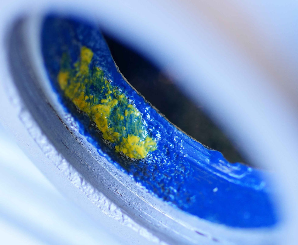
In Fig.37 & 38(below) you can see the aluminium behind the core plug has been corroded. The corrosion has just started to penetrate the sealing platform of the plug and so a leak is not far away.


In order to use the superior “cup” type plug rather than an inferior “dish” type core plug, the former having a greater surface sealing area, the aluminium requires machining as shown in Fig.39(below).

The image shows the newly machined surface and any corrosion removed ready to accept the new type core plug; the same can then be carried out for the opposing end of the head. No external rolling or burnishing is required with this type of plug and it is used widely in modern engines, using both cast iron and aluminium cylinder heads.
Corrosion – Head Gasket Face:
Surface corrosion (Fig.40(below)) around the water passages on the head gasket face can be repaired by Tig welding. Aluminium welding is very susceptible to impurities in the parent metal and it is this that makes the procedure problematic; oxidised, old cast aluminium is full of these impurities.
First of all, the corrosion needs to be dug out and cut back to good metal. The cylinder head is then pre-heated in an oven before welding can begin.

By welding around the coolant passage, the hole is unavoidably reduced in size (Fig.41(below)) as the metal repair builds up. Once cooled the cylinder head is mounted on a CNC milling machine and the coolant passage apertures are returned to the correct size. The machining procedure covers a couple of stages, whereby the first cut is a rough opening up the passageway which is then followed by a fine cut finish.

Once the welding repairs and CNC milling have been completed, the cylinder head gasket surface will require “Fly-Cutting” (skimming) to ensure it is flat and true; as in Fig.42(below). A tipped tool is the preferred and correct method here, as grinding or belt sanding is too course and will drag plus pluck the soft aluminium and create a grain. You must remember the single layer steel cylinder head gasket is relatively unforgiving and relies on a correct surface finish in order to seal effectively.

Cylinder Head Gaskets:
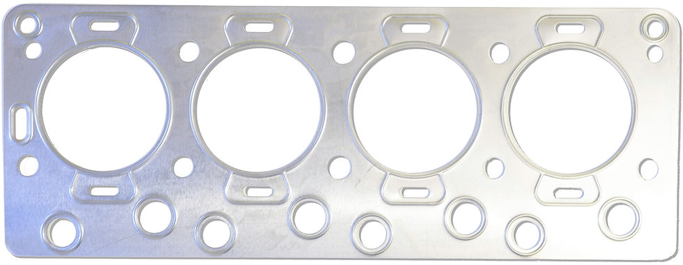
The standard cylinder head gasket (Fig.43(below)) is a single layer steel (SLS) item with embossed sealing crimps around the combustion chambers, water passages and push rod tubes. This gasket type is often criticised for its unforgiving nature, as it has a very simplistic construction.

That said “Simple is Efficient” !! The true reality is, it being a very effective sealing method that is now utilised in many modern engine designs. The main advantages over fibre or composite or copper gaskets are:
1- much stronger
2- high temperature resistance
3- no re-torquing required
4- will not slip, shear or blow under clamping force
5- compatible with additional sealant
6- there are not any real alternatives at the moment.
The main drawback that the SLS gasket has over fibre, composite or copper gaskets is that it has very little ability to conform to surface imperfections, warp or waviness within either the cast iron cylinder block or the aluminium cylinder head.
In Fig.44(below) you can see a library photo of a Daimler V8 cylinder head that has been re-surfaced using an abrasive linear belt machine. This type of machine is better suited to re-surfacing exhaust manifolds rather than cylinder heads. The image clearly shows a grain pattern forming with some deep irregular scratches. This is NOT the type of surface finish for which the SLS cylinder head gasket can cope – to be honest, would you want to see this finish on your engine block or cylinder head. Needless to say, leaks and blows will not be too far away.
The Importance of Surface Finish:
We have learnt that when using the single layer steel (SLS) cylinder head gasket, the surface finish of the cylinder head and block is critical in order to achieve a good long lasting seal. This is why the cylinder head gasket mating surfaces should be resurfaced in the correct way to ensure that a precise surface roughness is achieved. The SLS gasket requires a surface roughness of no more than 30uin (Micro Inches) Ra (Roughness Average) or 180Rz (Mean Roughness Depth). Smoother is always better for this type of gasket and can be into the low teen or single digit figures if achievable. Waviness should obviously be kept to an absolute minimum as should flatness. A Daimler V8 cylinder head has a maximum allowable “out of flat (warp)” of 0.004” / 0.1mm across its length and 0.002” / 0.05mm across the width. If all these tolerances can be met, the cylinder head can be sealed with the SLS gasket very effectively.

In Fig.45(below) you can see our cutaway cylinder head cross-section. It has been mounted on the resurfacing machine and fly-cut in the same as you would for a complete cylinder head that makes use of a SLS cylinder head gasket.

The first pass was at a depth of 0.002” and you can see where the cylinder head is still warped and out of shape – highlighted by the shading differences. In order to achieve the desired numbers for the surface finish we need to be able to measure surface roughness.
Once the surface of the cylinder head is flat and all the imperfections have been removed, we can test the surface with a profilometer, see Fig.46(below). This is a very accurate unit that will measure the minute peaks and valleys of the freshly machined cylinder head gasket face. You can see from the test results, on the profilometer, we are well within the recommended parameters which will enable the SLS head gasket to seal correctly and provide a long service life. Anything less, will NOT do and it is hugely important not to underestimate the importance of surface finish.

In the next instalment we shall look at valve guides, genuine K-line bronze guide liners and modified valve guides with stem seals.


Bình luận